


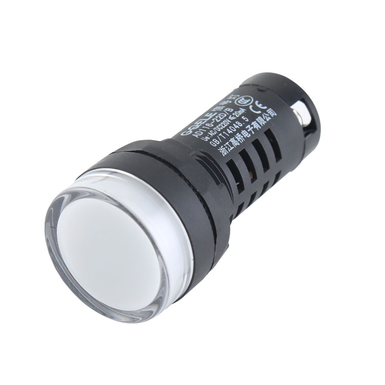
AD116-22D/B Φ22 Double Color Indicator Light With Black&White Shell
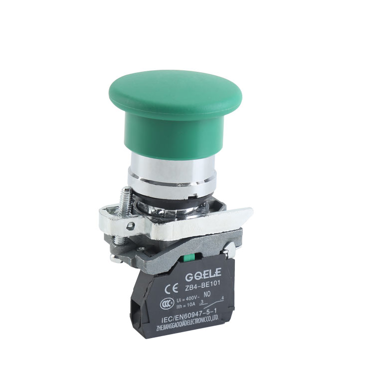
3.GXB4-BC31 High Quality 1NO Φ40 Mushroom Push Button Switch With Spring Return Action
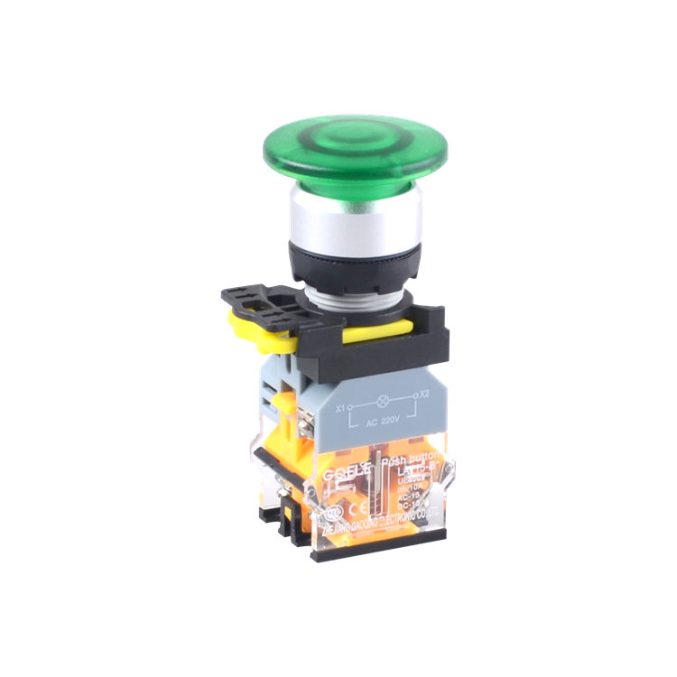
LA115-B2-11MD 1NO&1NC Momentary Illuminated Mushroom Push Button With Green Light
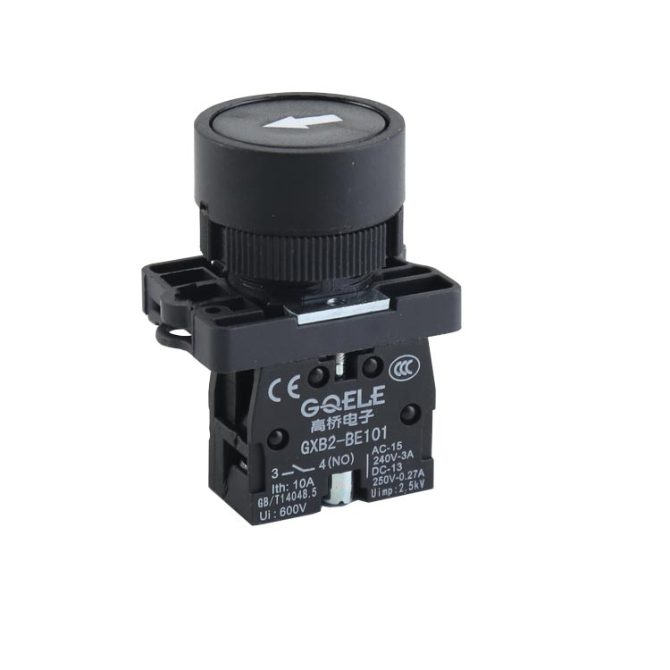
GXB2-EA3351 1NO Momentary Flush Push Button Switch With Round Shape Black Head And Symbol

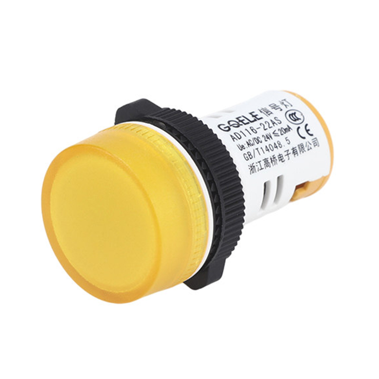
AD116-22CS Φ22 LED Indicator Light With Black Shell And Green Light

LA115-5-EBD Φ22 ~ Φ30 Momentary Adjustable Round Red Flush Push Button Head With Illumination And Symbol

LA115-N-11XD selector switch with LED light push button switch
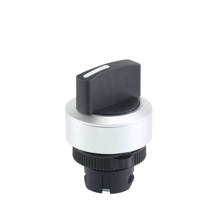
LA115-5-EX Φ22 ~ Φ30 2 Positions Adjustable Maintained Round Selector Push Button Head With Short Handle And No Light
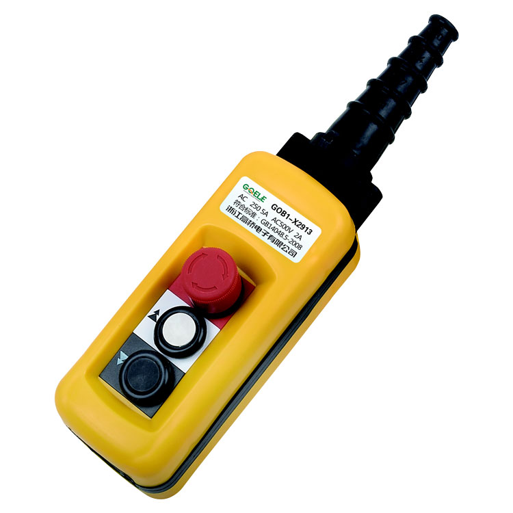
GOB1-X2913
Mini LED High Quality industrial Waterproof Pilot Light Signal Lamp Indicator Light Blue
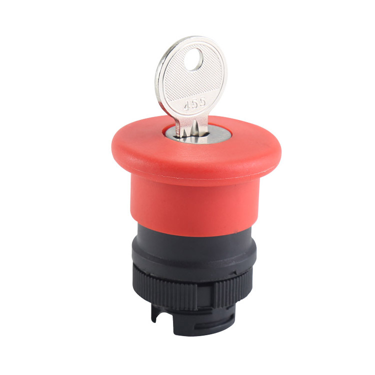
GXB2-ES14 Φ40 Red Key Control Mushroom Shape Emergency Stop Plastic Push Button Head With Key Rotating Release

LA115-A2-11Y High Quality 1NO&1NC Key Control Maintained 2-Position Keylock Push Button Switch With Round Head