We depend on sturdy technical force and continually create sophisticated technologies to meet the demand of push button electrical switch,
19MM Waterproof Flat Shape Screw Termina, We will continually strive to improve our service and provide the best quality products with competitive prices. Any inquiry or comment is highly appreciated. Please contact us freely. The product will supply to all over the world, such as, French, Customer's satisfaction is always our quest, creating value for customers is always our duty, a long term mutual-beneficial business relationship is what we are doing for. We are an absolutely reliable partner for yourself in China. Of course, other services, like consulting, can be offered too. A push button is a manually controlled master electrical appliance. It is mainly used to issue operation commands, turn
The button switch may be the simplest component in the electrical circuit, but it controls the lifeblood of the entire c
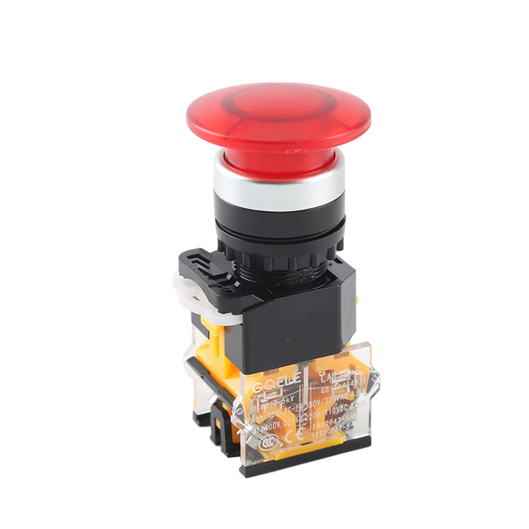
Start and stop button switch, generally used for start and stop. Generally, there are green, red, yellow and so on. We u
Wiring problem with button switch1. How to wire the button switch with light. There are five terminals on the button. No
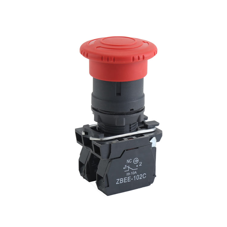
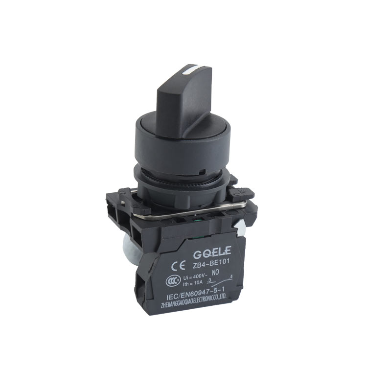
ClassificationClassified according to the purpose and structure of the contact (1) Normally open button (2) Normally clo
Signal indicator light, a device that uses light to monitor the working or position status of circuits and electrical eq
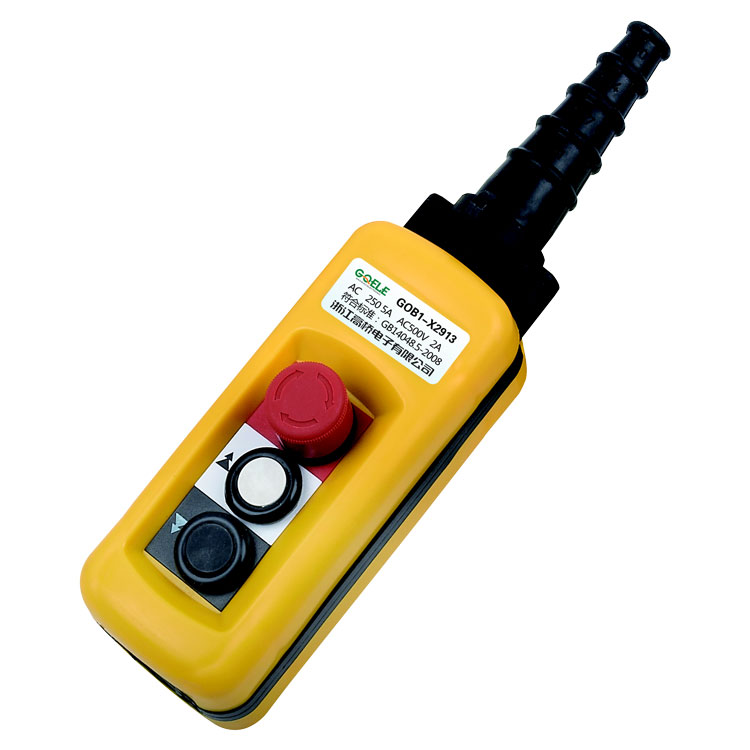
Waterproof push button switches, as the name suggests, are switches that can be operated with wet hands. In some humid e
GQEM provides high-quality push button switch products, including LED push button switches, metal push button switches, indicator lights and other types. With high sensitivity, stability and reliability, our push button switches are widely used in home appliances, automobiles, medical and other fields. Welcome to visit GQEM official website for more information.
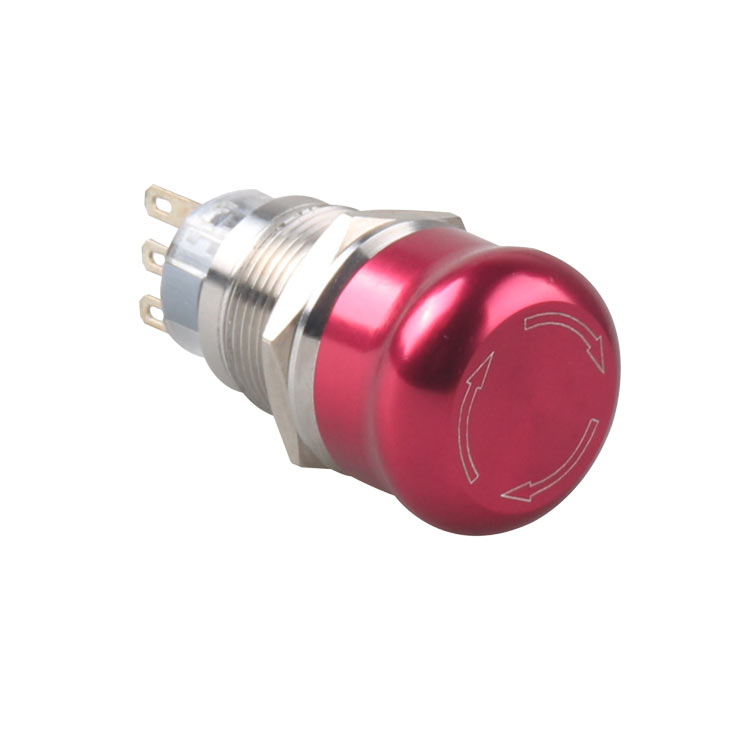
Stainless steel: Stainless steel has the characteristics of high strength, corrosion resistance, and high temperature resistance. It is one of the commonly used materials for making metal buttons. Aluminum alloy: The aluminum alloy material has the characteristics of lightness, high strength, and good thermal conductivity, and is often used to make metal buttons.
GQEM was founded in 2004, is an industrial production Professional manufacturer of product research and production. The main products are LED indicator, press Button, buzzer, PG waterproof connector, contactor and LED components, etc., It is widely used in control cabinets, power distribution cabinets, instrument cabinets and various control consoles.
The push button switch is a commonly used electrical control component, which is mainly used to control the switching state of the circuit. When the button is pressed, the switch will be closed, the circuit will be energized, and the electrical equipment will start to work; when the button is released, the switch will be turned off, the circuit will stop energizing, and the equipment will stop working.