


LA115-B1-11H High Quality 1NO & 1NC Momentary Extended Push Button With Round Shape Head And Without Light

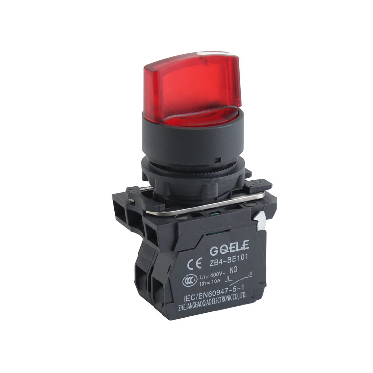
LA115-A1-11XD High Quality 1NO+1NC Maintained 2-Position Selector Push Button With Short Handle And Red Light

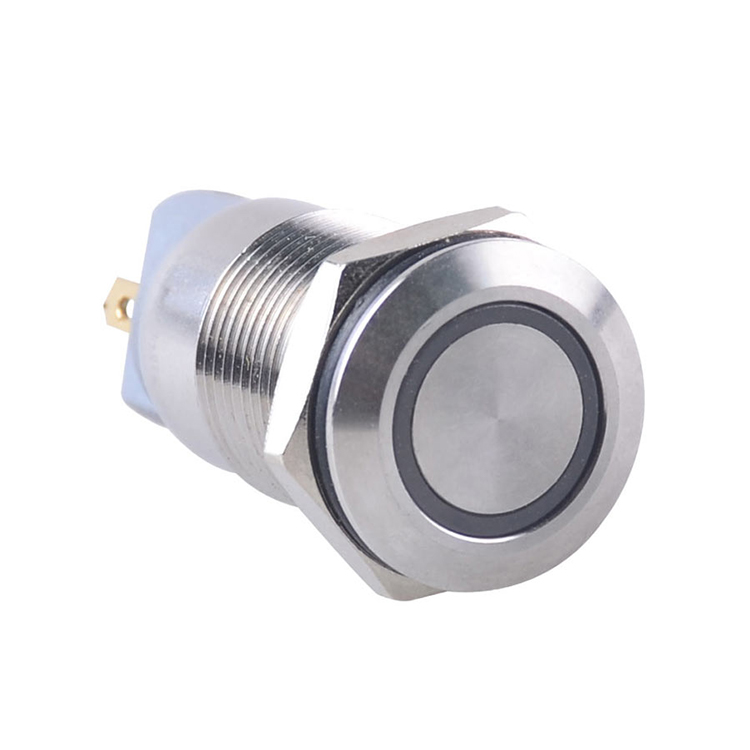
GL-22FE11S/G23-PJ

AD116-22DSV Red Green Yellow Voltage Led Indicator Light Pilot Plastic Signal Lamp Panel

LA115-N-11ZS 1NO&1NC Twist Release Emergency Stop Push Button With Mushroom Shape Head & Arrow Symbol

AL50-W-31Z2 High demand export products Continual light alarm flashing light

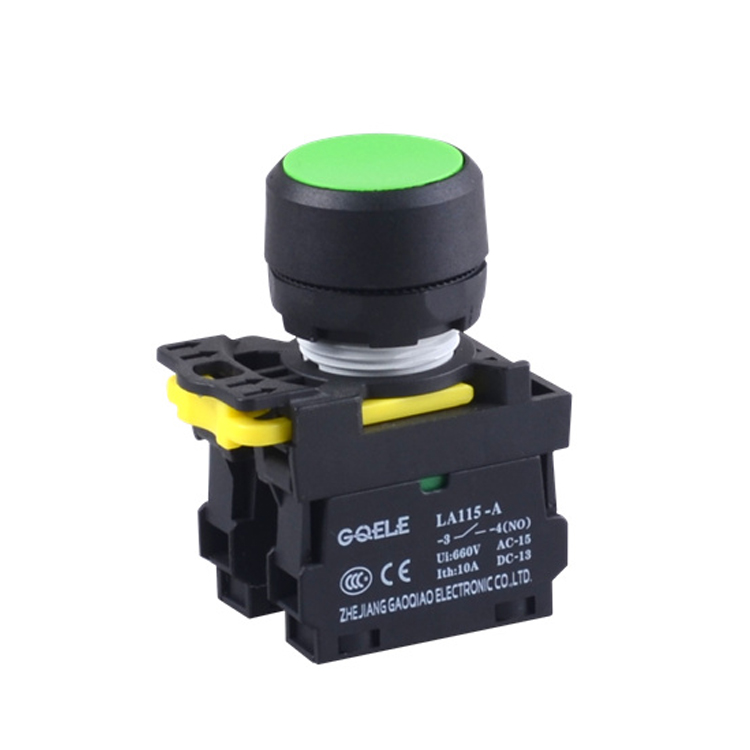
LA115-A5-11E 1NO+1NC High Quality Φ30 Momentary Flush Push Button With Round Green Head And Without Light
GXB4-EK3461 Red selector switch with LED light push button switch

LA115-A5-11M 1NO&1NC Momentary Plastic Mushroom Push Button With Red Head And Without Illumination

GOB-3A-GW
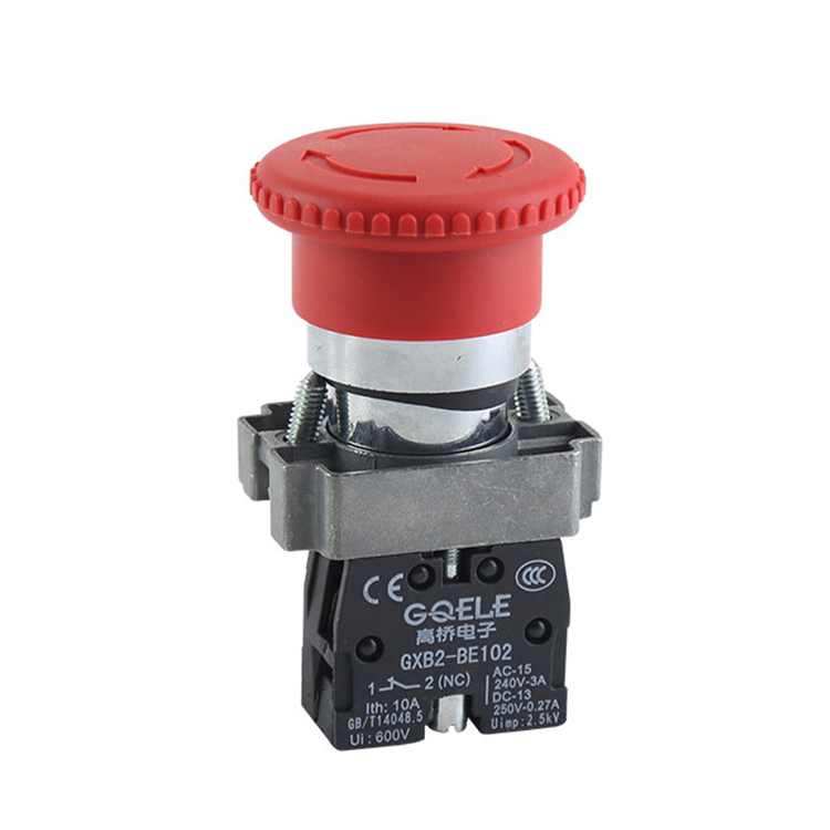
GXB2-BS542 Φ40 1NC Red Mushroom Shape Head Emergency Stop Push Button With Twist Release And Symbols

LA115-B9-11Y 1NO&1NC 2-Position High Quality Key Selector Push Button Switch With Self-locking & Key-operated Control And Round Aluminum Head