


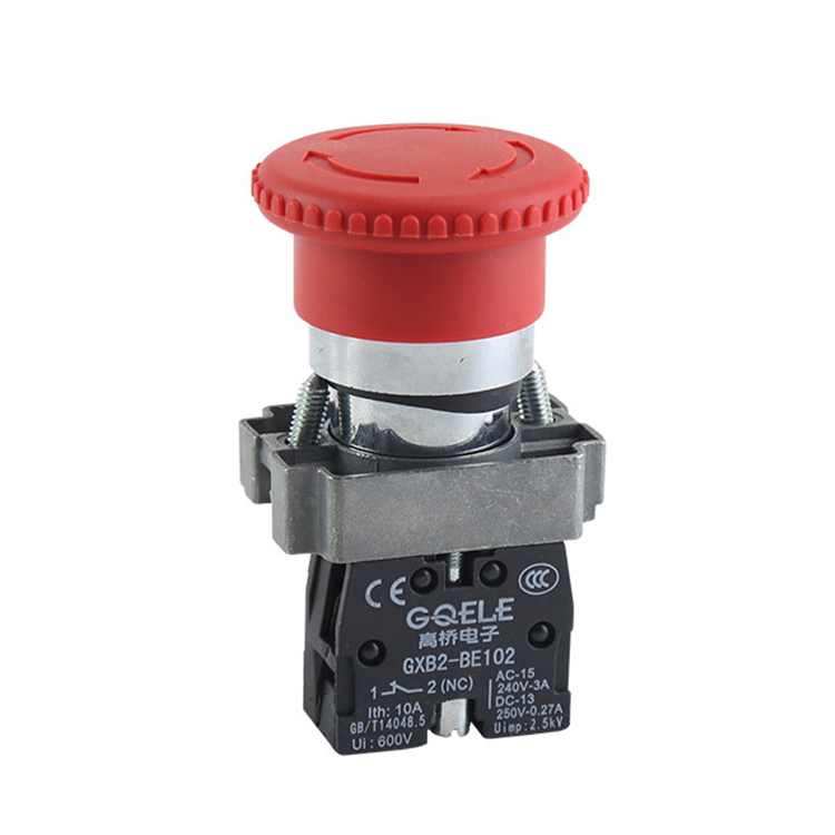
GXB2-BS542 Φ40 1NC Red Mushroom Shape Head Emergency Stop Push Button With Twist Release And Symbols
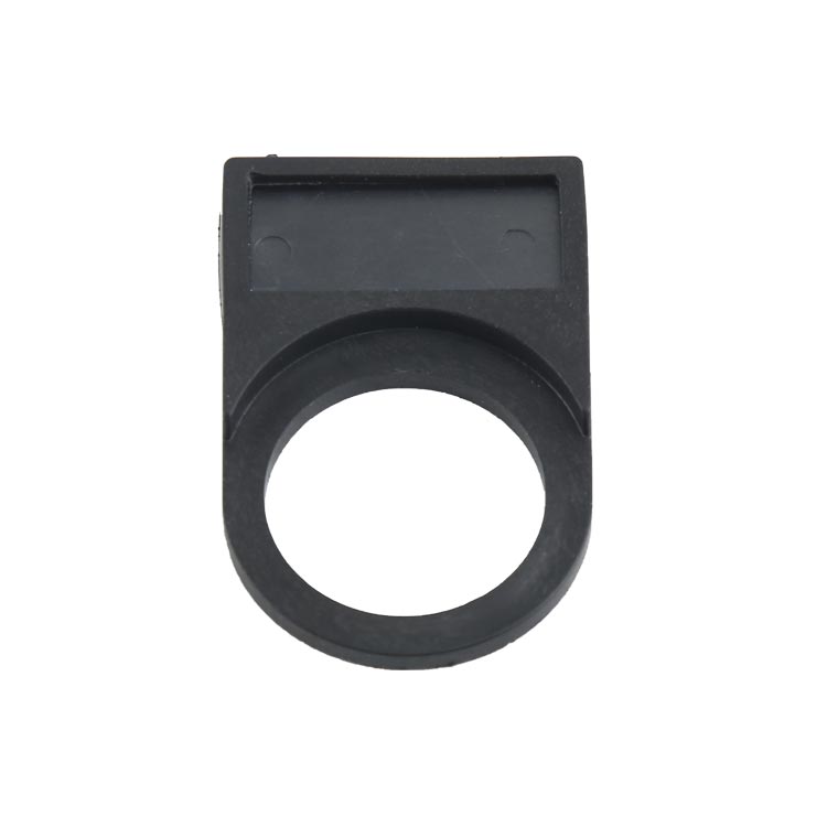
GXB2-EH2225 High Quality Black Plastic Label Holder For Labeling Plate

CJX2(LC1-D)-5011 3P+NO+NC 220V 380V 415V 660V cjx coil ac Electric magnetic contactor
GXB2-E
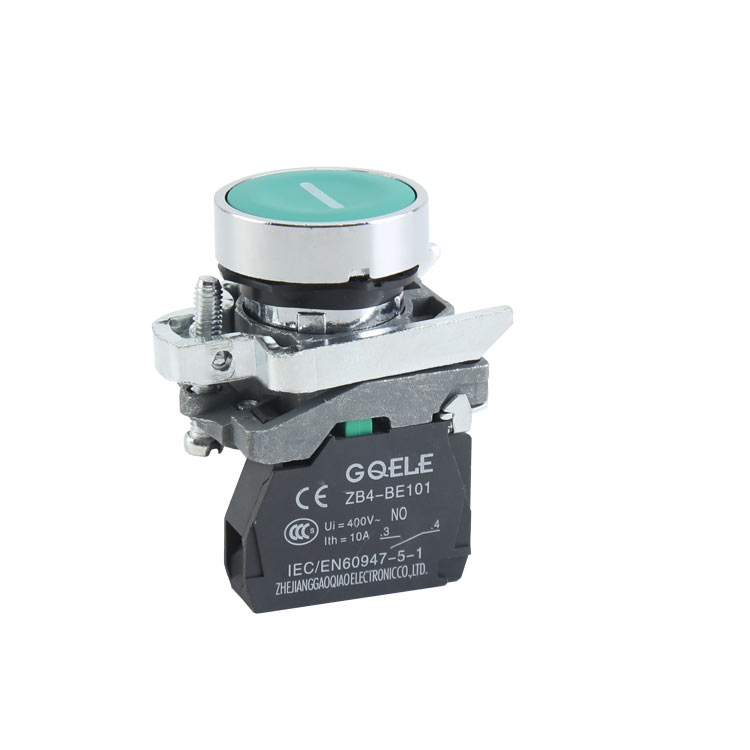
GXB4-BA3311 1NO Momentary Spring Return Flush Push Button With Round Shape Green Head And Symbol

BA9SG

LA115-A2-11CXD 1NO&1NC 2-Position Maintained Illuminated Selector Switch Push Button With Long Handle

GOB2-63
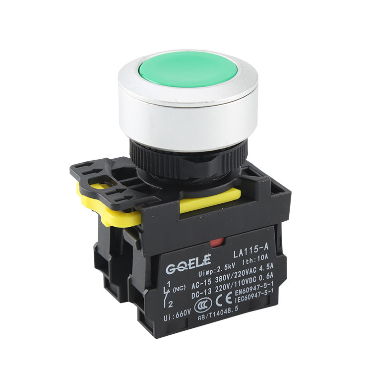
LA115-A5-11E 1NO+1NC High Quality Φ30 Momentary Flush Push Button With Round Green Head And Without Light

LA115-A1-11CX High Quality 1NO&1NC 2- Position Maintained Selector Push Button Switch With Long Handle And Without Illumination

AL70-RYG-31C5 Warning Light Tower Red Yellow Green LED Signal Tower Light Alarm Lamp Tower
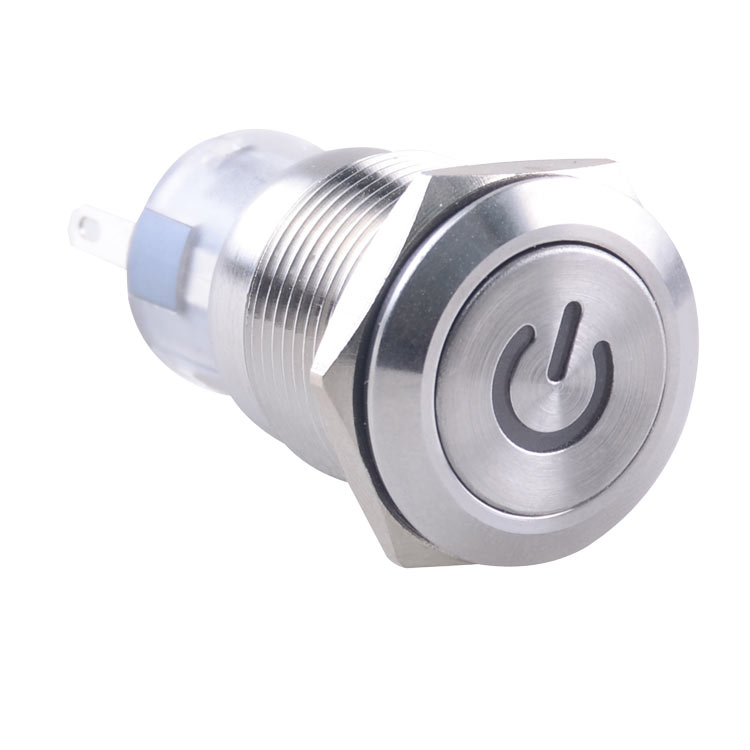
GL-19F11TS/R23-S