


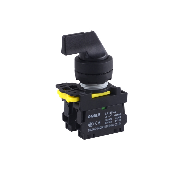
LA115-A1-11CX High Quality 1NO&1NC 2- Position Maintained Selector Push Button Switch With Long Handle And Without Illumination
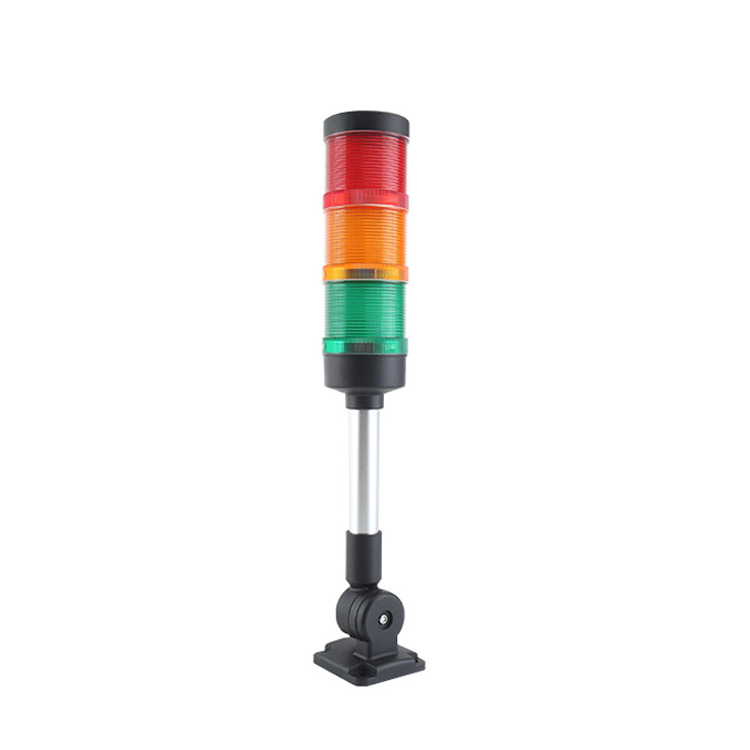
AL70-RYG-31Z4 Red&Yellow&Green Φ70 AC220V LED Modular Signal Tower Light For Machinery M4 Tri Color Without Buzzer With Foldable universal base

GXB2-ZB16F Black&Transparent Plastic Square Protective Cover To Prevent Dust And Water And Misoperation
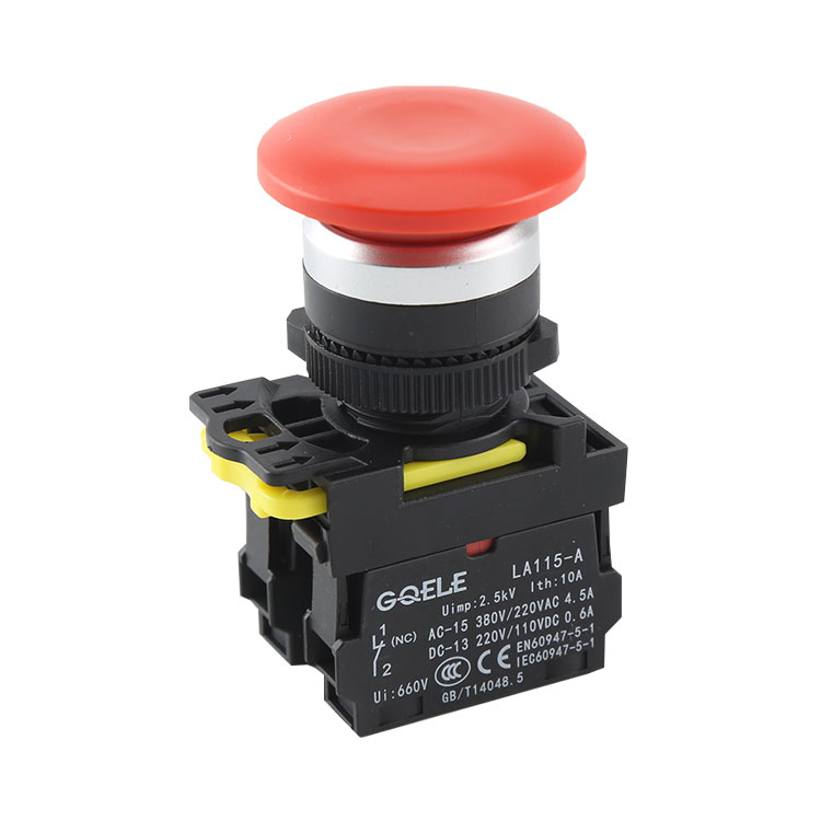
LA115-A5-11M 1NO&1NC Momentary Plastic Mushroom Push Button With Red Head And Without Illumination
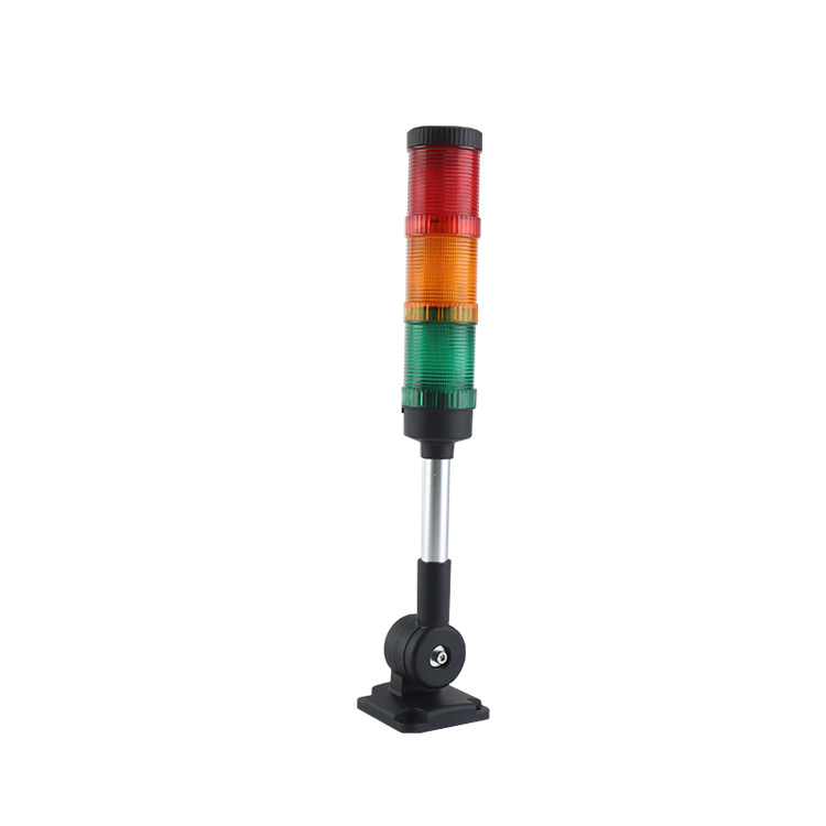
AL50-RYGM-31Z2 50MM LED Stack Warning Light With Buzzer

LA115-5-X Accessories

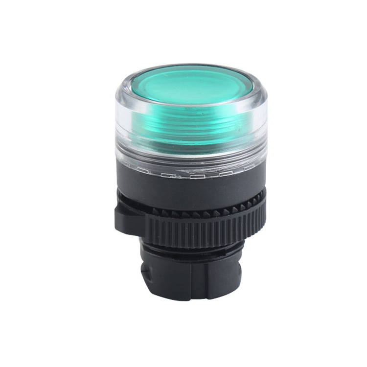
LA115-A2-11MD 1NO & 1NC Momentary & Illuminated Mushroom Push Button With Mushroom Shape Head And Green Light

GL-12BP11-SJ 12mm Waterproof self locking type metal push button switch LED with Ring light push button switch
LA115-5-HFD Illuminated Round Shape Momentary Higher Flush Push Button Head

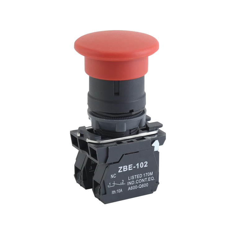
High Quality 1NO & 1NC Twist / Rotating Release Emergency Stop Push Button Switch With Mushroom Shape & Arrow Symbol Head And No Illumination
GXB4-EC45 High Quality 1NO+1NC Momentary Φ40 Mushroom Push Button With Mushroom Shape Red Head And Without Illumination

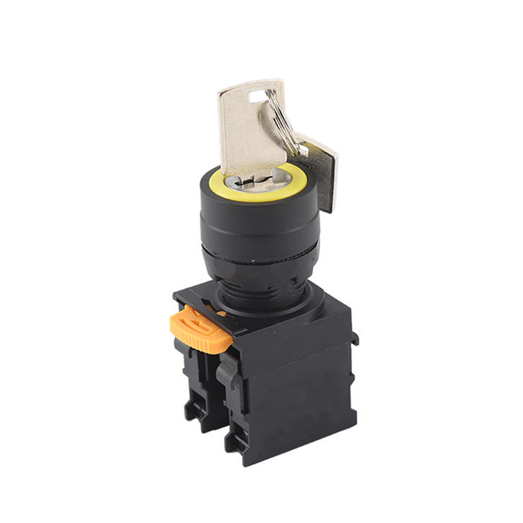
LA115-A5-11Y High Quality 1NO+1NC Key Control Maintained 2-Position Keylock Push Button Switch With Round Head