


GXB2-BL8434 1NO & 1NC Dual/Double Control Head Push Button Switch With Green & Red Extended And Marked Head And Without Light

AD116-22DS/MS High Quality Long-life Φ22 Flashing Buzzer With White&Black Shell And Red Light
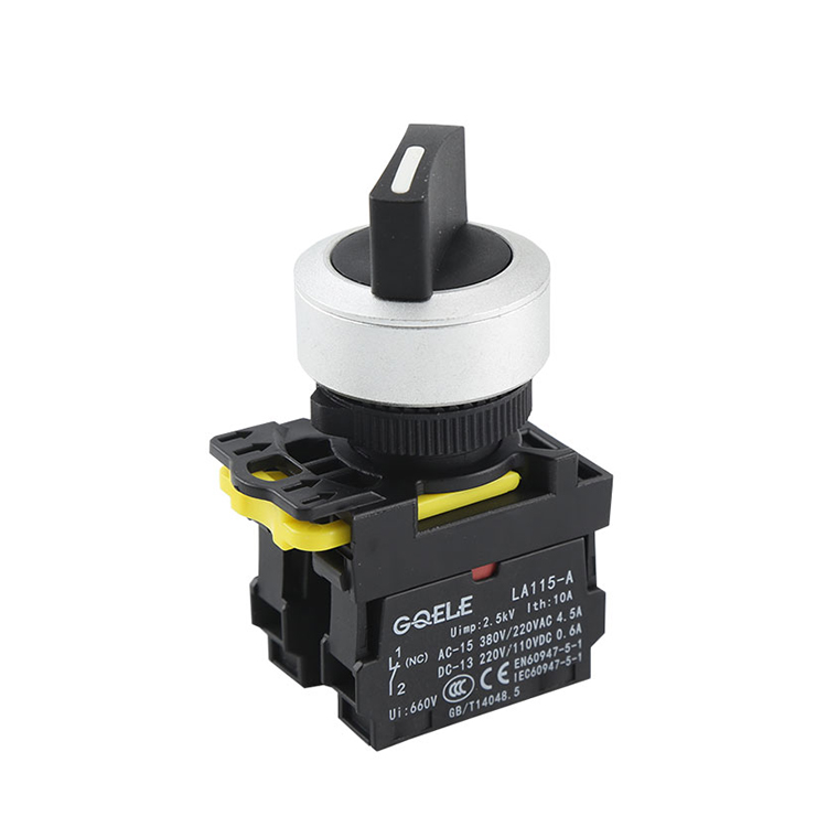
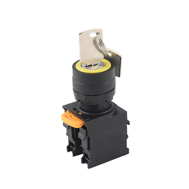
LA115-A5-11EX 1NO&1NC Maintained 2 Positions Selector Switch Push Button With Adjustable Round Head And Short Handle And Without Light

GL-22-HE11-SJ

LA115-K-11M High Quality 1NO&1NC Green Momentary Mushroom Plastic Push Button Without Light
Flush push button 22mm green pilot button indicator light switch GXB2-BA3341
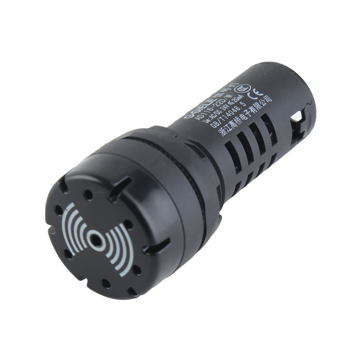
AD116-22D/M Φ22 High Quality PA66 Black&White Indicator Light With High Decibel Buzzer

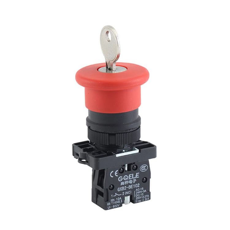
LA115-B5-11ZS 1NO&1NC Twist Release Emergency Stop Push Button With Mushroom Shape Head And Arrows

LA115-B5-11BD 1NO&1NC Momentary Flush Push Button Switch With Green Round Head And Symbol And Light

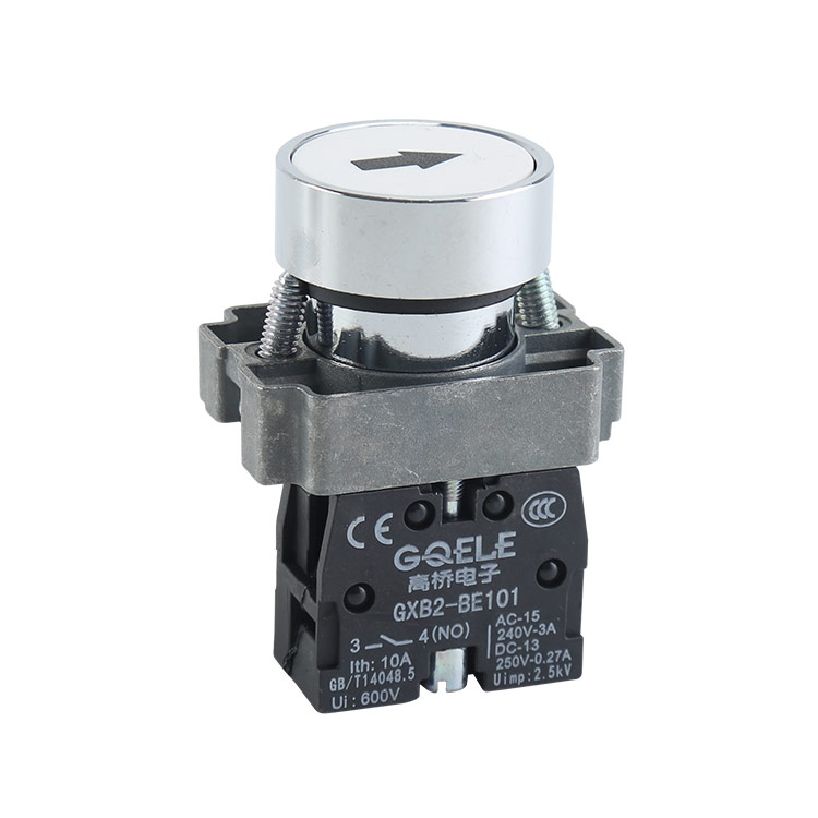
GL-22F11-SJ
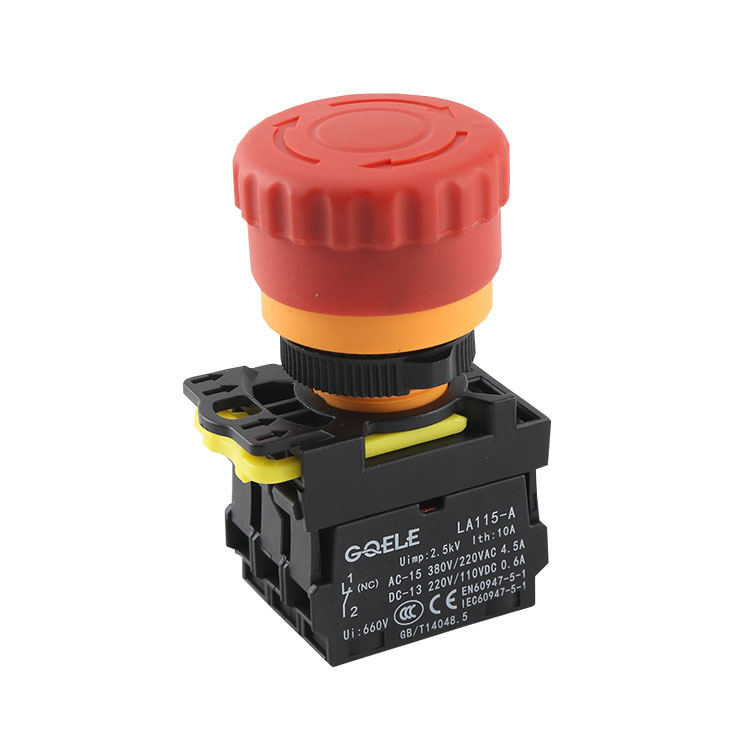
LA115-A5-11ZTD 1NO&1NC Twist Or Pull Release Illuminated Emergency Stop Push Button With Red Mushroom Shape Head And Symbols

AD116-22DSA High Quality Φ22 LED Current Indicator Light With Blackℜd Shell And Red Light